
What Is Electric Fan / Electric Fan And Winding Testing

Practical for electric fan winding and connection.
Identification and Analysis of Winding Wires in a Four-Wire Ceiling Fan Motor.
Aim: To Make a Connection and Identify the Starting winding, Running winding, and Common Windings in a Ceiling Fan.
Objective: To measure the resistance between motor windings and accurately identify the start (S), run (R), and common (C) terminals of a ceiling fan motor.
Apparatus Required:
- Digital Multimeter
- Insulated Connecting Wires
- Ceiling Fan Motor
- Safety Gloves
- Notepad and Pen for Recording Data.
Circuit Diagram
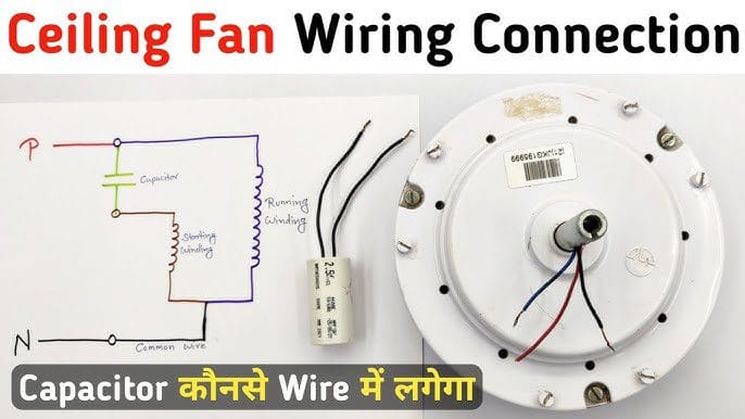
Key Components:
- Running) Winding(main): Connected directly to the AC power supply, this winding is responsible for the continuous operation of the motor.
- Starting) Winding: Connected in series with the capacitor, this winding provides the initial torque to start the motor and defines the direction of rotation.
- Capacitor: Typically an electrolytic capacitor, it creates a phase difference between the currents in the two windings, essential for starting the motor.
Operation:
For Electric Fan And Winding Testing When the switch is closed, AC voltage is applied to both the Running and Starting windings. The capacitor introduces a phase shift in the current through the Starting winding, creating a rotating magnetic field that starts the motor. Once the motor reaches its operating speed, the Running (main) winding maintains the rotation.
Procedure:
- Safety Precautions:
- Ensure the ceiling fan is completely disconnected from any power source.
- Wear safety gloves to prevent electrical hazards.
- Preparation:
- Label the three motor terminals as T1, T2, and T3 for identification purposes.
- Resistance Measurement:
- Set the digital multimeter to the resistance (ohms) setting.
- Measure and record the resistance between each pair of terminals:
- R(T1-T2)
- R(T1-T3)
- R(T2-T3)
- Data Analysis:
- Identify the pair of terminals with the highest resistance measurement; the terminal not involved in this pair is the Common (C) terminal.
- Between the common terminal and each of the other two terminals:
- The pair with the lowest resistance corresponds to the Run (R) winding.
- The pair with the intermediate resistance corresponds to the Start (S) winding.
Observation:
Resistance measurements:
- T1-T2 = 250 ohms
- T1-T3 = 165 ohms
- T2-T3 = 140 ohms
Analysis:
- The highest resistance (250 ohms) is between T1 and T2, so T3 is the Common (C) terminal.
- T2-T3 = 140 ohms (lowest resistance) → Run (R) winding.
- T1-T3 = 165 ohms (intermediate resistance) → Start (S) winding.
Conclusion:
By performing these resistance measurements and analyzing the results, you can accurately identify the start, run, and common windings of a ceiling fan motor. This information is crucial for proper wiring and troubleshooting of the motor.
Precautions:
- Ensure all connections are secure and conform to the circuit diagram to prevent loose connections, which can cause overheating or short circuits.
- Do not energize the circuit before verifying the connections with a qualified instructor or technician.
- Use insulated tools to prevent accidental electric shocks.
- Ensure that the power supply is turned off while making or modifying connections.
- Verify the ratings of all components to ensure they are suitable for the circuit.